
Phone: +86 15398058207
E-mail: sales@flexiturn.com
Add: Room 603 Building C, The Huixin Center, Zhangba One Road, Yanta Zone, Xi'an City, Shaanxi Province, China
What Causes Dimensional Variation in CNC Machined Parts?
What Causes Dimensional Variation in CNC Machined Parts?
Dimensional variation is a common concern in CNC machining, especially when a part has tight tolerances or needs to remain consistent across multiple production batches. At FlexiTurn, we manufacture non-standard CNC machined parts based on customer drawings, CAD files, and samples, with machining processes selected according to the part geometry, material, tolerance requirements, and production volume.
Even when the same CNC program is used, finished dimensions can sometimes vary from one part to another. Understanding the causes of this variation is important for controlling quality, reducing rework, and maintaining stable production.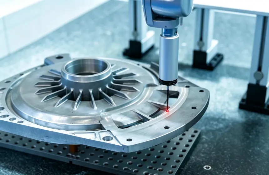
1. Tool Wear
Cutting tools gradually wear during machining. As the cutting edge becomes less sharp, it may remove slightly less material than expected, causing critical dimensions to shift.
Tool wear can be affected by material hardness, cutting speed, feed rate, depth of cut, coolant conditions, and production volume. Harder materials and long production runs can accelerate wear.
For parts with tight dimensional requirements, tool condition needs to be monitored and tools replaced or adjusted before the resulting wear affects the specified dimensions.
2. Thermal Expansion
Heat generated during cutting can affect both the workpiece and the machine components. When a metal part becomes warmer, its dimensions can change temporarily. Machine components and cutting tools can also experience thermal expansion during extended production.
This can become particularly important when machining large parts, tight-tolerance components, or performing long machining cycles.
Controlling cutting conditions, coolant, machine temperature, and measurement conditions can help reduce thermal-related dimensional variation.
3. Workholding and Fixturing
A workpiece must remain securely positioned throughout machining. If the fixture does not provide sufficient support, the part can move or deform under cutting forces.
Thin walls, long sections, and other flexible geometries are especially sensitive to workholding conditions. Excessive clamping force can also deform a relatively soft component, resulting in dimensions that change after the part is released from the fixture.
The fixture therefore needs to be selected according to the part's geometry, material, and machining sequence rather than simply holding the part as tightly as possible.
4. Material Properties
Different materials respond differently to machining forces and heat. Aluminum, stainless steel, tool steel, brass, engineering plastics, and other materials can require different cutting strategies.
Internal stresses in the material can also be released during machining. This may cause a part to deform after material is removed, particularly when machining large pockets, thin sections, or asymmetrical components.
Selecting an appropriate material condition and machining sequence can help maintain dimensional stability.
5. Machine Accuracy and Stability
The CNC machine itself can contribute to dimensional variation. Factors such as machine calibration, axis positioning accuracy, backlash, spindle condition, and mechanical wear can affect machining results.
For multi-axis machining, the relationship between different axes becomes particularly important when producing complex geometries or features that must maintain accurate positional relationships.
Regular machine maintenance and appropriate process verification are therefore important for stable production.
6. Programming and Toolpath Errors
Incorrect tool offsets, work coordinate settings, tool compensation, or machining parameters can directly affect part dimensions.
The machining sequence also matters. Removing a large amount of material in an unsuitable order can introduce deformation or leave uneven machining forces that affect the final dimensions.
For complex components, engineers need to consider the complete machining process rather than focusing only on the final cutting operation.
7. Measurement Conditions
Not every dimensional difference is caused by the machining process itself. Measurement methods can also introduce variation.
Temperature, measuring equipment, operator technique, fixture positioning, and measurement resolution can all affect inspection results. A dimension measured immediately after machining may also differ slightly from one measured after the part has reached a stable temperature.
For critical dimensions, appropriate inspection equipment and consistent measurement procedures are necessary to distinguish actual machining variation from measurement variation.
8. Machining Sequence and Part Deformation
The order in which features are machined can have a significant effect on dimensional stability.
For example, removing a large amount of material from one side of a component may release internal stress and cause the remaining structure to deform. A suitable roughing, stress-relief, semi-finishing, and finishing strategy can reduce this effect.
For complex or thin-walled parts, the machining sequence should be considered during process planning rather than treated as an afterthought.
How Can Dimensional Variation Be Reduced?
Controlling dimensional variation requires more than simply using a high-accuracy CNC machine. The entire manufacturing process needs to work together.
A practical approach includes:
- Selecting suitable cutting tools and machining parameters
- Monitoring tool wear during production
- Controlling workholding and clamping forces
- Using an appropriate machining sequence
- Considering material characteristics and deformation risks
- Maintaining stable machine conditions
- Checking tool and work offsets
- Using suitable inspection equipment and consistent measurement methods
- Performing dimensional inspection at critical stages of production
At FlexiTurn, CNC machining processes are selected according to the specific requirements of each non-standard component. CNC milling, turning, 3-axis, 4-axis, and 5-axis machining can be used according to part geometry and production requirements, while dimensional inspection and CMM measurement can be applied when tighter inspection requirements are needed.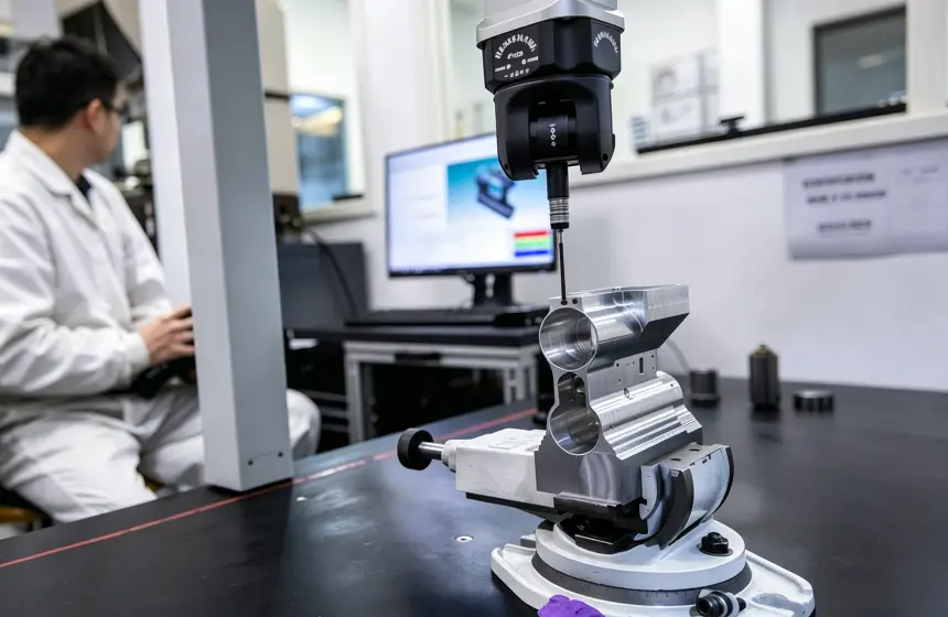
Conclusion
Dimensional variation in CNC machined parts can result from many factors, including tool wear, thermal expansion, workholding, material behavior, machine condition, programming, machining sequence, and measurement methods. In practice, these factors can also interact with each other, making process control important for maintaining consistent dimensions.
For manufacturers purchasing custom CNC machined parts, clearly defined drawings, tolerances, material requirements, and inspection requirements provide an important foundation for stable production. Working with a manufacturer that evaluates these requirements during process planning can also help reduce dimensional variation before it becomes a production problem.
- What Causes Dimensional Variation in CNC Machined Parts?
- CNC Machining Tolerances: What Accuracy Does Your Part Really Need?
- Why Do CNC Machining Quotes Differ Between Suppliers?
- How to Prepare a CNC Machining Drawing for Manufacturing?
- How Does Part Geometry Affect CNC Machining Cost?
- Why Are Small Internal Radii Difficult to CNC Machine?
- How Do Deep Pockets Affect CNC Machining?
- Common CNC Machining Design Mistakes That Increase Cost