
Phone: +86 15398058207
E-mail: sales@flexiturn.com
Add: Room 603 Building C, The Huixin Center, Zhangba One Road, Yanta Zone, Xi'an City, Shaanxi Province, China
How to Prepare a CNC Machining Drawing for Manufacturing?
At FlexiTurn, CNC machining projects often begin with a customer drawing, CAD file, or sample. Before production starts, our engineers need to understand not only the finished shape of the part, but also the material, critical dimensions, tolerances, surface requirements, and inspection expectations.
A well-prepared CNC machining drawing gives the manufacturer the information needed to produce the part correctly and helps avoid unnecessary questions, quotation differences, and production delays.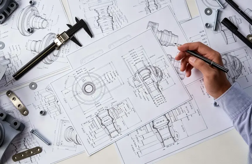
So, what should a CNC machining drawing include?
1. Clearly Define the Finished PartThe drawing should clearly show the complete geometry of the finished component.
Include sufficient views to describe features that may not be visible from the main view, such as holes, pockets, steps, grooves, threads, or features on the opposite side.
For more complex components, sectional or detailed views can be useful. If a feature is difficult to understand from the drawing alone, a 3D CAD model can provide additional reference.
The goal is simple: the manufacturer should be able to understand the intended final geometry without having to guess.
2. Specify the MaterialAlways identify the required material and grade when it is important to the part's function.
For example, aluminum, stainless steel, steel, brass, copper, titanium, and engineering plastics have different machining characteristics and material costs.
The material specification also helps the supplier determine suitable tooling, machining parameters, finishing methods, and starting stock.
If the material condition or specific material requirement matters to the application, it should also be stated clearly rather than left to the supplier's assumption.
3. Identify Critical DimensionsNot every dimension on a part has the same functional importance.
Clearly dimension the features that affect assembly, movement, alignment, sealing, or interaction with other components. These may include hole locations, diameters, mating surfaces, overall dimensions, and critical thicknesses.
Avoid relying on visual proportions or dimensions that can be interpreted in multiple ways. A manufacturer should not have to estimate an important dimension from the drawing.
4. Apply Tolerances Where They MatterTolerances tell the manufacturer how much variation is acceptable.
Functional features may require tighter tolerances, while non-critical dimensions can often use more practical general tolerances.
Applying very tight tolerances to every dimension can increase machining time, inspection requirements, and overall cost without necessarily improving the part.
A better approach is to identify the dimensions that are genuinely critical to the part's function and specify appropriate tolerances for them.
5. Define Threads, Holes, and Special FeaturesThreaded holes and other machined features should be clearly specified.
For holes, provide the required diameter, depth, location, and other relevant information. Threads should identify the applicable thread type and size rather than relying on the manufacturer to determine them.
Features such as counterbores, countersinks, reamed holes, grooves, or keyways should also be clearly defined.
These details can directly affect tooling and machining operations, so incomplete specifications may result in additional clarification before production.
6. Specify Surface Finish and TreatmentIf the part requires a particular surface finish or treatment, include it in the drawing or associated specifications.
Depending on the application, requirements may include anodizing, polishing, sandblasting, electroplating, or another surface treatment.
It is also useful to distinguish between functional surfaces and cosmetic surfaces. Not every surface needs the same appearance or treatment, and making this distinction can help control manufacturing cost.
7. Show Datums and Important RelationshipsFor components with multiple critical features, the relationship between those features can be more important than an individual dimension.
Datums and appropriate geometric tolerances can help communicate how the part should be measured and how important surfaces or features relate to one another.
This is particularly relevant for components that must align with shafts, bearings, fasteners, mating housings, or other assemblies.
A clear datum structure also helps the manufacturer establish an appropriate machining and inspection approach.
8. Include Inspection RequirementsIf certain dimensions or geometric characteristics require specific inspection, state the expectation clearly.
For example, a project may require CMM inspection for critical dimensions or feature relationships. If inspection reports are required, this should also be communicated before production.
Clear inspection requirements help the supplier understand the expected quality level and include the appropriate inspection work when preparing the quotation.
9. Provide the CAD File When AppropriateA 2D drawing is often the primary manufacturing reference, while a 3D CAD file can provide additional information about complex geometry.
For parts involving curved surfaces, multi-axis features, or complicated profiles, providing both a drawing and CAD model can reduce ambiguity.
At FlexiTurn, customers can provide drawings, CAD files, or samples for non-standard CNC machining. Using these references together can help engineers better understand the intended part before machining begins.
10. Consider Manufacturing Before Finalizing the DrawingA drawing should define what the finished part needs to be, but it is also worth considering whether the design is practical to manufacture.
Features such as extremely deep pockets, very thin walls, unnecessarily tight tolerances, difficult internal corners, or complex setups can increase machining difficulty and cost.
A manufacturing review before production can identify these issues early. In some cases, a small design adjustment can simplify machining without changing the functional purpose of the component.
This is where DFM and engineering support can provide value before material is put on the machine.
What a CNC Manufacturer Needs From Your DrawingA practical CNC machining drawing should clearly communicate the finished geometry, material, important dimensions, tolerances, threads and holes, surface requirements, datums, and inspection expectations.
The more clearly these requirements are defined, the less room there is for different manufacturing assumptions.
For complex parts, providing the drawing together with a 3D CAD file and any relevant samples or assembly information can give the manufacturer a more complete understanding of the project.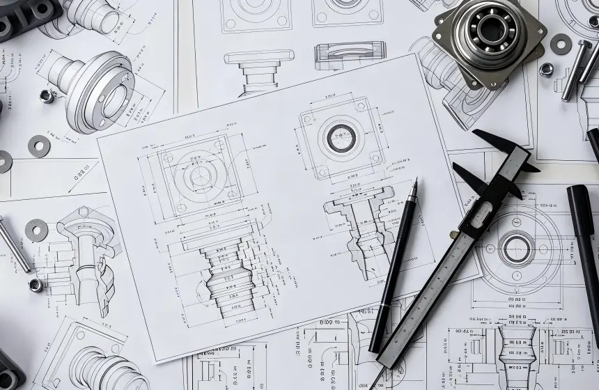
FlexiTurn provides non-standard CNC machining based on customer drawings, CAD files, or samples.
Our engineers review the provided information to understand the part geometry, material, machining requirements, and production quantity before determining a suitable manufacturing approach. Depending on the component, this may involve CNC milling, CNC turning, 3-axis, 4-axis, or 5-axis machining, together with required inspection and surface treatment.
For prototypes and small-batch production, this early engineering review can be especially useful. It helps identify potential manufacturing issues before production and provides a clearer basis for quoting and process planning.
Final ThoughtsA good CNC machining drawing does more than show the shape of a part. It communicates what the finished component needs to achieve and which characteristics are important to its function.
Clearly defined geometry, material, tolerances, critical features, surface requirements, and inspection expectations can reduce misunderstandings and make CNC manufacturing more predictable.
If a component is complex, reviewing the drawing with the manufacturer before production can also help identify practical DFM improvements and potential cost drivers early in the process.
- Why Do CNC Machining Quotes Differ Between Suppliers?
- How to Prepare a CNC Machining Drawing for Manufacturing?
- How Does Part Geometry Affect CNC Machining Cost?
- Why Are Small Internal Radii Difficult to CNC Machine?
- How Do Deep Pockets Affect CNC Machining?
- Common CNC Machining Design Mistakes That Increase Cost
- How Can DFM Reduce CNC Machining Cost?
- What Is DFM in CNC Machining and Why Does It Matter?